Product classification


限扭 The torque limiter
Production and manufacture of standard fastener pins and keys; Non-standard precision cylinder, special-shaped column key, inch fine (thick) steel key strip.
key word:Keys、Pins
Classification:
Product Description
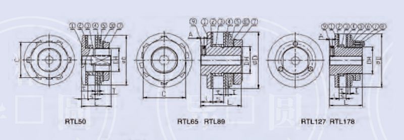
Part Name Parts:
1. Main Hub
2. Friction plate Friction Plate
3、称环Lining Ring
4、压板 Pressure Plate
5. Disc Spring
6. Pilot Plate
7. Adjusting nut Adjusting Nut
8. Adjusting bolt Adjusting Bolt
9. Locking screw Locking Screw
10. Stop gasket Gaskot
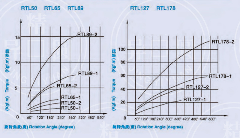
Set the Rotation Angle and Torque
Selection SELECTION
1. According to the load conditions or the size of the equipment itself to determine the required slip torque. If the equipment load condition is not clear, set the slip torque to the motor output
1.5-2 times the torque on the shaft carrying the torque limiting device.
2. When selecting the torque limiting device, the torque range and aperture range should be large enough.
3. According to the thickness of the center element of the two friction plates, the most suitable width of the backing ring is determined.
The required sliding torque is set depends upon the loading or the force of the equipment. If the loading conditions are not clear, please set the sliding to que as 1.5-2 times of one upon the shaft that carries the Torque Limiter. Please select the Torque Limiter with sufficient torque and aperture ranges.
Select optimum lining ring length according to the center part thickness clamped between the two friction discs.
Torque setting TORQUESETTING
The torque of the torque-limiting device is set by tightening and loosening the adjusting bolt and/or the adjusting nut. For RTL50 to RTL89, rely on the adjusting nut; for RTL127 and RTL178, rely on the adjusting bolt.
Tight and loose the adjusting bolts and/or nuts to set the torque of the Torque Limiter. The Limiter form size RTL50 to RTL89 depend upon the adjusting nuts, whereas RTL127 and RTL178 depends upon the adjusting bolts.
The torque can be set after the torque limiting device is installed on the shaft. The process is as follows:
Set the torque after mounting the Limiter upon the shaft as follow:
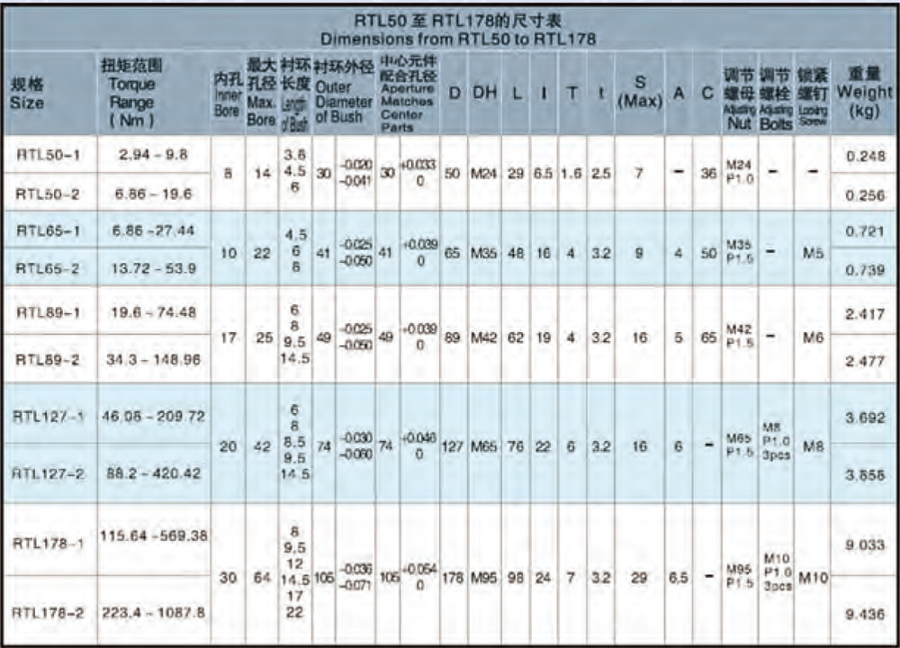
Specifications of RTL50 to RTL89
For sizes form RTL50 to RTL89
First, tighten the adjusting nut by hand, so as to fix the disc spring and the pressure plate;
Rotate to tight the adjusting nuts by hands to fix the disc spring and plate;
Then, try to tighten the nut with a wrench, about 60 degrees.
Then, try to tight the nuts (about 60℃)by wrench
Specifications of RTL127 to RTL178
ForsizesformRTL127toRTL178
First, rotate the nut, fix the disc spring and the pressure plate, and then tighten each adjusting bolt, about 60 degrees.
First, rotate the nuts to tight the disc spring and pressure plate. Then tight all the adjusting bolts (about 60℃)
Then, if the torque limiting device can slip under normal load conditions, gradually tighten the nut (RTL50 to RTL89) or bolt (RTL127 to RTL178) until the torque limiting device stops slipping. Be sure to tighten (or loosen) each bolt evenly.
If the Limiter slides with normal loading,please tight the nuts (for sizes form RTL50 to RTL89) or bolts (form RTL127 to RTL178) generally until the Limiters stop sliding. Please ensure that each bolt is tightened or lossened averagely.
Through such several tests, to find suitable for the equipment of the limited torque setting. The following table shows the relationship between the effective rotation angle and the limit setting for reference.
Find out the setting torque appropriate for the equipments after tests. Please refer the following Table that shows
the relationship between the effective rotation angle and torque setting.
For accurate torque setting, a test run of the torque limiting device is recommend. For example, at a speed of 50-60rpm and 500 rpm, rotate the adjusting nut and cargo bolt 45 degrees.
To make torque setting precisely, we recommend you to use Torque Limiter for trial once. For example, while the rotation speed is 50-60 rpm with 500 circles, rotate the adjusting nuts or bolts around 45℃
CENTERPARTS center element
1. The friction surface of the center original should be processed to ensure the rated torque, as well as flatness, parallelism, consistency with the hole, rust and oil. The recommend surface roughness was Ra 1.6. If the center element cannot meet the above technical requirements, the slip torque will be unstable.
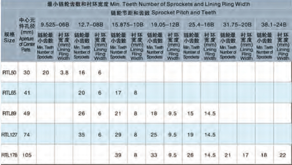
2. Please follow the table to machine the hole of the center element, and select the minimum number of sprocket teeth and the width of the backing ring.
Process the friction face of center parts to ensure the rated torque, planeness and parallelism in line with the bore and protect the parts from the rust and oil. The recommended surface roughness(Ra) is 1.6. The sliding torque will be not stable if the center part is defected.
Please process the bore of center parts according to the following Table and, select sprocket with min. teeth number and lining ring length.
Production and manufacture of standard fastener pins and keys; Non-standard precision cylinder, special-shaped column key, inch fine (thick) steel key strip; Special-shaped key parts, transmission expansion sleeve and torque-limited products; High-pressure water pump; Professional enterprise of mechanical processing service. Among them: pin, key two series of 13 varieties thousands of models and specifications, and to undertake the special requirements of users of non-standard parts and stainless steel pins, keys and other products customized production. Production has a history of forty years. There are 70 employees, including 15 engineering and technical personnel and various professional management personnel, accounting for 21% of the total number of employees. Enterprise covers an area of 8000 square meters, construction area of 4000 square meters. The production capacity of the enterprise is 30 million pieces. Products in accordance with international standards for production, enterprises through the ISO9001:2000 version of the quality management system certification.
recommend products


recommend products
Welcome to leave a message for consultation

Manufacturing standard fastener pins and keys; Non-standard precision cylindrical, high-pressure water pumps; professional enterprises of mechanical processing services, to undertake the customized production of non-standard parts and stainless steel pins, keys and other products required by users.
Nantong Jingyiyuan Mechanical and Electrical Standard Parts Manufacture Co., Ltd.

Official website
Official website
All rights reserved©2024 Nantong Jingyi Yuan Electromechanical Standard Parts Manufacturing Co., Ltd.SEO
Website construction:China Enterprise Power Nantong Business License